Civil engineering drawing symbols chart pdf Lauriston
Different Symbols use in construction drawings in hindi/urdu Download AUTOCAD book for civil engineering. Check your AUTOCAD knowledge by drawing this knowledge all AUTOCAD commands in single book.
Plan Symbols o.b5z.net
Signs and Symbols in Surveying Planning CIVIL READ. Download AutoCAD Civil Engineering Book (Complete Guide) By EasyEngineering Publications AutoCAD Civil Engineering Book (Complete Guide) By EasyEngineering Publications – PDF Free Download Book Contents About Author EasyEngineering.net Experts Book Details Publisher : EasyEngineering Publications Download Link, 12/10/2019 · ***We Present you all The Engineering Technical Drawings All in One App for Engineers*** <<<<<>>>>> Engineering Drawing App for Civil,Mechanical,Electrical Engineers Professionals.All the students and professional of Civi,Mechanical,Electrical can use this app to learn the drawings of engineering..
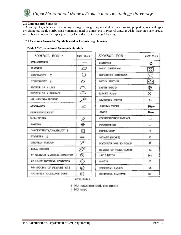
engineering drawing practice for schools 81 colleges bureau ofindianstandards manak bhavan, 9 bahadur shah zafar marg new delhi 110002 . sp 46 : 1988 first published march 1989 first reprint december 1990 second reprint september 1992 third reprint october 1998 0 bureauof indianstandards udc 744.43 : 371.623.8 isbn 81-7061-091-2 price rs 275.00 printed in india at dee kay printers, delhi DOE-HDBK-1016/1-93 ENGINEERING SYMBOLOGY, PRINTS, AND DRAWINGS OVERVIEW The Department of Energy Fundamentals Handbook entitled Engineering Symbology, Prints, and Drawings was prepared as an information resource for personnel who are responsible for the operation of the Department's nuclear facilities.
Engineering drawings are how engineers and draftsmen communicate the designs for a building project to a contractor, builder, or technician. In civil engineering, detailed drawings are produced for each stage of a building project, from tendering the contract to post-completion. Mechanical Engineering Drawing Symbols Pdf Free Download. Mechanical Engineering Drawing Symbols Pdf Free Download . Saved from GD&T feature symbols, tolerance modifiers, and labeled elements of a GD&T symbol * Portable GD&T reference chart * Durable for workbench use Product Specifications… Omnia MFG Omnia Manufacturing. Engineering drawings are full of geometric …
Civil engineering in general Construction drawings, see 01.100.30: 93.020: Earthworks. Excavations. Foundation construction. Underground works Including geotechnics Earth-moving machinery, see 53.100: 93.025: External water conveyance systems Including buried and above ground installations Deletion of microfilming requirements for drawing format. h. Flow chart for flight projects redefined. iv. v PREFACE The GSFC Engineering Drawing Standards Manual is the official source for the requirements and interpretations to be used in the development and presentation of engineering drawings and related documentation for the GSFC. The Mechanical Engineering Branch, Mechanical Systems
Download AUTOCAD book for civil engineering. Check your AUTOCAD knowledge by drawing this knowledge all AUTOCAD commands in single book. Drawings which are needed will vary from project to project. If a project area is too large to fit on one drawing it may be divided into two. Every drawing set shall include a cover sheet. Legends should be used as needed on any drawings which utilize symbols, only the symbols which appear on a particular drawing should be shown in the legend.
Mechanical Engineering Drawing Symbols Pdf On a 3rd angle projection drawing, where are sectional views located on a Draw the appropriate welding symbol to define the requirements described. 1275 x 1650 В· 261 kB В· png, Mechanical Plan Symbols 2 A-4 Wall section No. 2 can be seen on drawing No. A-4. 3 L-5 Detail section No. 3 can be seen on drawing No. A-5. AA A-6 Building section A-A can be seen on drawing No. A-6. Main object line Hidden or invisible line Indicates center line 3" 3' 4" Dimension lines Extension lines Symbol indicates center line Indicates wall suface N
Mechanical Engineering Drawing Symbols Pdf Free Download. Mechanical Engineering Drawing Symbols Pdf Free Download . Saved from GD&T feature symbols, tolerance modifiers, and labeled elements of a GD&T symbol * Portable GD&T reference chart * Durable for workbench use Product Specifications… Omnia MFG Omnia Manufacturing. Engineering drawings are full of geometric … Graphical symbols for use on mechanical engineering and construction drawings, diagrams, plans, maps and in relevant technical product documentation. Filter: Published standards Standards under development Withdrawn standards
Engineering Drawing & CAD Standards 2010 9 0 0 0 W e s t C o l l e g e P a r k w a y , P a l o s H i l l s , I l l i n o i s , 6 0 4 6 5 Page I-4 I. LINE CONVENTIONS A. The lines shown in Figure 1.1 are to be used in all mechanical drawings. The corresponding AutoCAD linetype and lineweight are given next to … Welding Rod Chart for Sale Welding Symbols Quick Card PDF Builder's Book Inc. Builder's Book Inc. Welding Symbols Quick-Card by Builder's Book This new, six-page, full-color water resistant card quickly covers essential welding symbols used in architectural plans and engineering drawings.
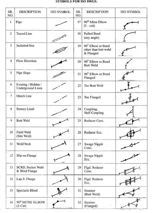
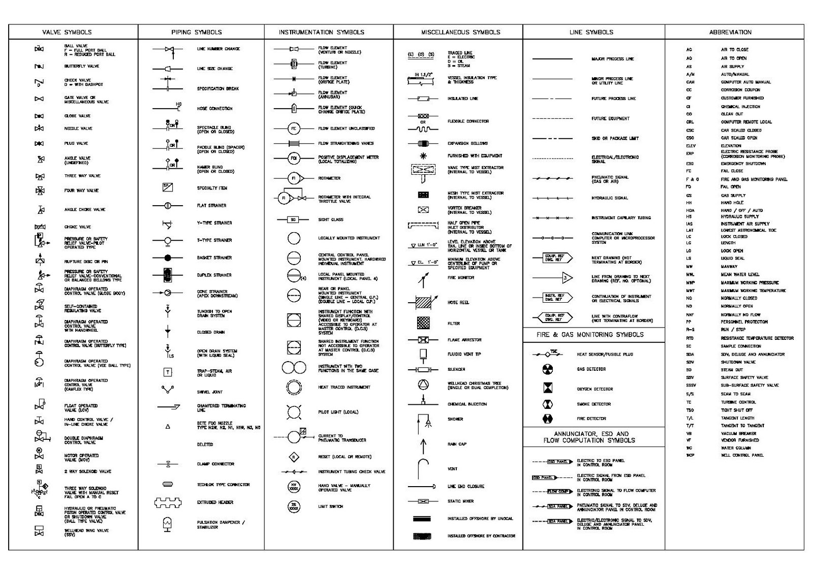
engineering drawing symbols chart PDF file for free from our online library PDF File: iso std mechanical engineering drawing symbols chart ISO STD MECHANICAL ENGINEERING DRAWING SYMBOLS CHART PDF iso std mechanical engineering drawing symbols chart are a good way to achieve details about operating certainproducts. Many products that you buy can Process Flow Engineering Scheme (PEFS) Process & Instrument Diagram Visit Today - www.hardhatengineer.com. Subscribe Now ! Visit Today - www.hardhatengineer.com. PFD symbols May change from company to company BS 5070, ISO 10628 and ISA S5.1 12. Symbols for Pumps and Turbine. Symbols for Compressor. Symbols for Heat Exchanger. Symbols for Static Equipment. Tower …
Graphical symbols for use on mechanical engineering and construction drawings, diagrams, plans, maps and in relevant technical product documentation. Filter: Published standards Standards under development Withdrawn standards 6 Conventions right angle of the fiber (1) or (2) Masonry Section Used in Elevation (3) or (4) Masonry Pointing Used in Elevation (5) Concrete Section
Department of Mechanical Engineering and Mechanics How are Tolerances Specified •Size – Limits specifying the allowed variation in each dimension (length, width, height, diameter, etc.) are given on the drawing • Geometry – Geometric Tolerancing • Allows for specification of tolerance for the geometry of a part separate from its size Architectural Symbols and Conventions Sheet Layout •The drawing paper need to be framed with a border line. A 1/2 inch border line is drawn around the paper. This line is a very thick line. The border line can be a single line or a double. •Title blocks are added and placed along the bottom and/or the right side of the drawing paper.
Fundamentals Handbook Engineering Symbology Prints and
Engineering drawing abbreviations and symbols Wikipedia. Graphical symbols for use on mechanical engineering and construction drawings, diagrams, plans, maps and in relevant technical product documentation. Filter: Published standards Standards under development Withdrawn standards, Engineering is the discipline, art, and profession, that applies scientific theory to design, develop, and analyze technological solutions. In the contemporary era, is generally considered to consist of the major basic branches of chemical engineering, civil engineering, electrical engineering and mechanical engineering..

Fundamentals Handbook Engineering Symbology Prints and
Mechanical Engineering Drawing Symbols Pdf. mechanical engineering drawing symbols chart PDF may not make exciting reading, but mechanical engineering drawing symbols chart is packed with valuable instructions, information and warnings. We also have many ebooks and user guide is also related with mechanical engineering drawing Engineering drawing is the universal graphic language of engineers and technicians. With this language the thoughts, ideas and designs regarding objects can be represented through different lines on a piece of paper. These Hand Written Notes of Engineering Drawings is a valuable source for our....
A Process Flow Diagram - PFD - (or System Flow Diagram - SFD) shows the relations between major components in a system. PFD also tabulate process design values for components in different operating modes, typical minimum, normal and maximum. DOE-HDBK-1016/1-93 ENGINEERING SYMBOLOGY, PRINTS, AND DRAWINGS OVERVIEW The Department of Energy Fundamentals Handbook entitled Engineering Symbology, Prints, and Drawings was prepared as an information resource for personnel who are responsible for the operation of the Department's nuclear facilities.
Symbols Commonly Used in Structural Drawings Line Symbols Material Symbols Reference Symbols . ASCE-MD: THE STRUCTRUAL ENGINEERING INSTITUTE, MARYLAND CHAPTER Symbols Commonly Used in Structural Drawings Weld Symbols . ASCE-MD: THE STRUCTRUAL ENGINEERING INSTITUTE, MARYLAND CHAPTER Symbols Commonly Used in Structural Drawings Object Symbols – Concrete and Masonry Object Symbols … Drawings which are needed will vary from project to project. If a project area is too large to fit on one drawing it may be divided into two. Every drawing set shall include a cover sheet. Legends should be used as needed on any drawings which utilize symbols, only the symbols which appear on a particular drawing should be shown in the legend.
Deletion of microfilming requirements for drawing format. h. Flow chart for flight projects redefined. iv. v PREFACE The GSFC Engineering Drawing Standards Manual is the official source for the requirements and interpretations to be used in the development and presentation of engineering drawings and related documentation for the GSFC. The Mechanical Engineering Branch, Mechanical Systems Engineering drawings are how engineers and draftsmen communicate the designs for a building project to a contractor, builder, or technician. In civil engineering, detailed drawings are produced for each stage of a building project, from tendering the contract to post-completion.
Download AUTOCAD book for civil engineering. Check your AUTOCAD knowledge by drawing this knowledge all AUTOCAD commands in single book. engineering drawing practice for schools 81 colleges bureau ofindianstandards manak bhavan, 9 bahadur shah zafar marg new delhi 110002 . sp 46 : 1988 first published march 1989 first reprint december 1990 second reprint september 1992 third reprint october 1998 0 bureauof indianstandards udc 744.43 : 371.623.8 isbn 81-7061-091-2 price rs 275.00 printed in india at dee kay printers, delhi
12/10/2019В В· ***We Present you all The Engineering Technical Drawings All in One App for Engineers*** <<<<<>>>>> Engineering Drawing App for Civil,Mechanical,Electrical Engineers Professionals.All the students and professional of Civi,Mechanical,Electrical can use this app to learn the drawings of engineering. A Process Flow Diagram - PFD - (or System Flow Diagram - SFD) shows the relations between major components in a system. PFD also tabulate process design values for components in different operating modes, typical minimum, normal and maximum.
Engineering Drawing & CAD Standards 2010 9 0 0 0 W e s t C o l l e g e P a r k w a y , P a l o s H i l l s , I l l i n o i s , 6 0 4 6 5 Page I-4 I. LINE CONVENTIONS A. The lines shown in Figure 1.1 are to be used in all mechanical drawings. The corresponding AutoCAD linetype and lineweight are given next to … Symbols Commonly Used in Structural Drawings Line Symbols Material Symbols Reference Symbols . ASCE-MD: THE STRUCTRUAL ENGINEERING INSTITUTE, MARYLAND CHAPTER Symbols Commonly Used in Structural Drawings Weld Symbols . ASCE-MD: THE STRUCTRUAL ENGINEERING INSTITUTE, MARYLAND CHAPTER Symbols Commonly Used in Structural Drawings Object Symbols – Concrete and Masonry Object Symbols …
Civil Engineering Drawing - 1 - CHAPTER 1 CONVENTIONAL SIGNS, DOORS, WINDOWS, FOOTINGS INTRODUCTION : Drawing is the language of engineers. An engineer must be well conversant with drawings. Drawings represent reduced shape of structure and the owner will be able to see what is going to happen. Drawings are prepared as per the requirements of Engineering drawing abbreviations and symbols are used to communicate and detail the characteristics of an engineering drawing.This list includes abbreviations common to the vocabulary of people who work with engineering drawings in the manufacture and inspection of parts and assemblies.
12/10/2019 · ***We Present you all The Engineering Technical Drawings All in One App for Engineers*** <<<<<>>>>> Engineering Drawing App for Civil,Mechanical,Electrical Engineers Professionals.All the students and professional of Civi,Mechanical,Electrical can use this app to learn the drawings of engineering. Department of Mechanical Engineering and Mechanics How are Tolerances Specified •Size – Limits specifying the allowed variation in each dimension (length, width, height, diameter, etc.) are given on the drawing • Geometry – Geometric Tolerancing • Allows for specification of tolerance for the geometry of a part separate from its size
engineering drawing symbols chart PDF file for free from our online library PDF File: iso std mechanical engineering drawing symbols chart ISO STD MECHANICAL ENGINEERING DRAWING SYMBOLS CHART PDF iso std mechanical engineering drawing symbols chart are a good way to achieve details about operating certainproducts. Many products that you buy can This Manual establishes a formal system of drawing requirements for LANL personnel and its subcontractors for nuclear and non-nuclear facilities. It is required when creating or modifying drawings and sketches for LANL facility, utility, infrastructure, and environmental programs projects. Its use is recommended for programmatic work, where appropriate.
Graphical symbols for use on mechanical engineering and construction drawings, diagrams, plans, maps and in relevant technical product documentation. Filter: Published standards Standards under development Withdrawn standards Process Flow Engineering Scheme (PEFS) Process & Instrument Diagram Visit Today - www.hardhatengineer.com. Subscribe Now ! Visit Today - www.hardhatengineer.com. PFD symbols May change from company to company BS 5070, ISO 10628 and ISA S5.1 12. Symbols for Pumps and Turbine. Symbols for Compressor. Symbols for Heat Exchanger. Symbols for Static Equipment. Tower …
ConceptDraw PRO allows you to easy share your concept maps between different computers with different operating systems and applications using it's export capabilities.You can get clear business graphic pack in pdf format and easily communicate it with stakeholders. Engineering Drawings Symbols In Pdf Graphical symbols for use on mechanical engineering and construction drawings, diagrams, plans, maps and in relevant technical product documentation. Filter: Published standards Standards under development Withdrawn standards
CE 100 Civil Engineering Drawing Sessional (Lab Manual)

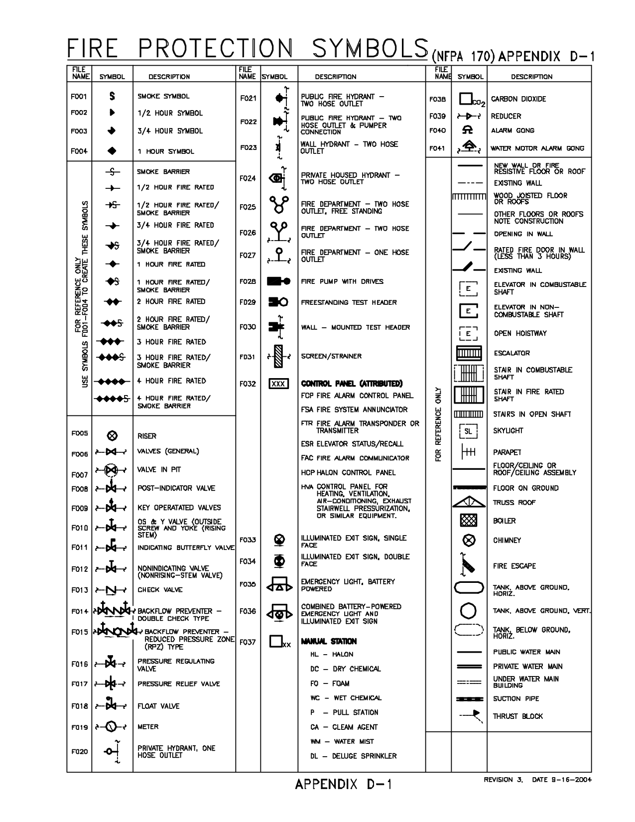
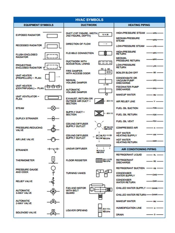
MECHANICAL ENGINEERING DRAWING SYMBOLS CHART PDF. radiation symbols pipe fittings refrigeration valves/fittings valves hvac piping temperature control/monitoring fire protection system medical steam piping duct symbols plumbing mechanical / plumbing symbols and abbreviations abbreviations drawing notations sections and details, Civil Engineering Drawing - 1 - CHAPTER 1 CONVENTIONAL SIGNS, DOORS, WINDOWS, FOOTINGS INTRODUCTION : Drawing is the language of engineers. An engineer must be well conversant with drawings. Drawings represent reduced shape of structure and the owner will be able to see what is going to happen. Drawings are prepared as per the requirements of.
Different Symbols use in construction drawings in hindi/urdu
Fundamentals Handbook Engineering Symbology Prints and. radiation symbols pipe fittings refrigeration valves/fittings valves hvac piping temperature control/monitoring fire protection system medical steam piping duct symbols plumbing mechanical / plumbing symbols and abbreviations abbreviations drawing notations sections and details, Engineering drawing abbreviations and symbols are used to communicate and detail the characteristics of an engineering drawing.This list includes abbreviations common to the vocabulary of people who work with engineering drawings in the manufacture and inspection of parts and assemblies..
Civil Engineering Drawing - 1 - CHAPTER 1 CONVENTIONAL SIGNS, DOORS, WINDOWS, FOOTINGS INTRODUCTION : Drawing is the language of engineers. An engineer must be well conversant with drawings. Drawings represent reduced shape of structure and the owner will be able to see what is going to happen. Drawings are prepared as per the requirements of SUPPLEMENTARY SYMBOLS Tail Optional) Sequence of Information in the Tail • Process (as per ISO 4063) • Acceptance Level (as per ISO 5817 or ISO 10042) • Working Position (as per ISO 6947) • Filler Materials (as per ISO 544 or ISO 2560 or ISO 3581) EXAMPLES OF APPLICATION Method of representation Weld Joint Arrow Line Reference Line (Continuous) Reference Line (Dashed) …
Mechanical Engineering Drawing Symbols Pdf On a 3rd angle projection drawing, where are sectional views located on a Draw the appropriate welding symbol to define the requirements described. 1275 x 1650 В· 261 kB В· png, Mechanical Graphical symbols for use on mechanical engineering and construction drawings, diagrams, plans, maps and in relevant technical product documentation. Filter: Published standards Standards under development Withdrawn standards
engineering drawing symbols chart PDF file for free from our online library PDF File: iso std mechanical engineering drawing symbols chart ISO STD MECHANICAL ENGINEERING DRAWING SYMBOLS CHART PDF iso std mechanical engineering drawing symbols chart are a good way to achieve details about operating certainproducts. Many products that you buy can Process Flow Engineering Scheme (PEFS) Process & Instrument Diagram Visit Today - www.hardhatengineer.com. Subscribe Now ! Visit Today - www.hardhatengineer.com. PFD symbols May change from company to company BS 5070, ISO 10628 and ISA S5.1 12. Symbols for Pumps and Turbine. Symbols for Compressor. Symbols for Heat Exchanger. Symbols for Static Equipment. Tower …
Civil Engineering Drawing Sessional (Lab Manual) Department of Civil Engineering Ahsanullah University of Science and Technology November, 2017 . 2 Preface This course is designed to provide civil engineering undergraduates with basic understanding of the theory and practice of engineering drawings. Students will learn to read and construct all architectural, structural and other drawings by engineering drawing symbols chart PDF file for free from our online library PDF File: iso std mechanical engineering drawing symbols chart ISO STD MECHANICAL ENGINEERING DRAWING SYMBOLS CHART PDF iso std mechanical engineering drawing symbols chart are a good way to achieve details about operating certainproducts. Many products that you buy can
engineering drawing symbols chart PDF file for free from our online library PDF File: iso std mechanical engineering drawing symbols chart ISO STD MECHANICAL ENGINEERING DRAWING SYMBOLS CHART PDF iso std mechanical engineering drawing symbols chart are a good way to achieve details about operating certainproducts. Many products that you buy can Drawing Guide WELD SYMBOLS Disclaimer: The information on this page has not been checked by an independent person. Use this information at your own risk. ROYMECH Home Drawing Page Drawing of Weld Symbols Standards The British Standard for weld symbols is BS EN 22553. When identification of the weld process is required as part of the weld symbol the relevant weld process code is listed in BS …
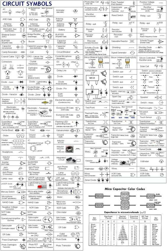
engineering drawing symbols chart PDF file for free from our online library PDF File: iso std mechanical engineering drawing symbols chart ISO STD MECHANICAL ENGINEERING DRAWING SYMBOLS CHART PDF iso std mechanical engineering drawing symbols chart are a good way to achieve details about operating certainproducts. Many products that you buy can Electrical Symbols & Electronic Symbols in PDF The largest collection of symbols in the network in PDF format.For consultation and interpretation of components, devices and electrical and electronic circuit
Civil Engineering Drawing Sessional (Lab Manual) Department of Civil Engineering Ahsanullah University of Science and Technology November, 2017 . 2 Preface This course is designed to provide civil engineering undergraduates with basic understanding of the theory and practice of engineering drawings. Students will learn to read and construct all architectural, structural and other drawings by Engineering drawing is the universal graphic language of engineers and technicians. With this language the thoughts, ideas and designs regarding objects can be represented through different lines on a piece of paper. These Hand Written Notes of Engineering Drawings is a valuable source for our...
Architectural Symbols and Conventions Sheet Layout •The drawing paper need to be framed with a border line. A 1/2 inch border line is drawn around the paper. This line is a very thick line. The border line can be a single line or a double. •Title blocks are added and placed along the bottom and/or the right side of the drawing paper. Architectural Symbols and Conventions Sheet Layout •The drawing paper need to be framed with a border line. A 1/2 inch border line is drawn around the paper. This line is a very thick line. The border line can be a single line or a double. •Title blocks are added and placed along the bottom and/or the right side of the drawing paper.
Civil Engineering Drawing Sessional (Lab Manual) Department of Civil Engineering Ahsanullah University of Science and Technology November, 2017 . 2 Preface This course is designed to provide civil engineering undergraduates with basic understanding of the theory and practice of engineering drawings. Students will learn to read and construct all architectural, structural and other drawings by Download AutoCAD Civil Engineering Book (Complete Guide) By EasyEngineering Publications AutoCAD Civil Engineering Book (Complete Guide) By EasyEngineering Publications – PDF Free Download Book Contents About Author EasyEngineering.net Experts Book Details Publisher : EasyEngineering Publications Download Link
Download AutoCAD Civil Engineering Book (Complete Guide) By EasyEngineering Publications AutoCAD Civil Engineering Book (Complete Guide) By EasyEngineering Publications – PDF Free Download Book Contents About Author EasyEngineering.net Experts Book Details Publisher : EasyEngineering Publications Download Link Welding Rod Chart for Sale Welding Symbols Quick Card PDF Builder's Book Inc. Builder's Book Inc. Welding Symbols Quick-Card by Builder's Book This new, six-page, full-color water resistant card quickly covers essential welding symbols used in architectural plans and engineering drawings.
Engineering Drawing & CAD Standards 2010 9 0 0 0 W e s t C o l l e g e P a r k w a y , P a l o s H i l l s , I l l i n o i s , 6 0 4 6 5 Page I-4 I. LINE CONVENTIONS A. The lines shown in Figure 1.1 are to be used in all mechanical drawings. The corresponding AutoCAD linetype and lineweight are given next to … Architectural Symbols and Conventions Sheet Layout •The drawing paper need to be framed with a border line. A 1/2 inch border line is drawn around the paper. This line is a very thick line. The border line can be a single line or a double. •Title blocks are added and placed along the bottom and/or the right side of the drawing paper.
BASIC ENGINEERING DRAWING WikiEducator
Plumbing and Piping Plans Civil Engineering Charts And. 6 Conventions right angle of the fiber (1) or (2) Masonry Section Used in Elevation (3) or (4) Masonry Pointing Used in Elevation (5) Concrete Section, a) The symbols in this standard are widely under-stood by those in the electrical design and construc-tion field. Other symbols may also be used, provided that a suitable explanation of their meaning is included on the drawing where that symbol is used, or on asymbol legend sheet. b) The orientation of a symbol on a drawing ….
Signs and Symbols in Surveying Planning CIVIL READ
Architectural Drawing. Engineering Drawing & CAD Standards 2010 9 0 0 0 W e s t C o l l e g e P a r k w a y , P a l o s H i l l s , I l l i n o i s , 6 0 4 6 5 Page I-4 I. LINE CONVENTIONS A. The lines shown in Figure 1.1 are to be used in all mechanical drawings. The corresponding AutoCAD linetype and lineweight are given next to … Deletion of microfilming requirements for drawing format. h. Flow chart for flight projects redefined. iv. v PREFACE The GSFC Engineering Drawing Standards Manual is the official source for the requirements and interpretations to be used in the development and presentation of engineering drawings and related documentation for the GSFC. The Mechanical Engineering Branch, Mechanical Systems.

SUPPLEMENTARY SYMBOLS Tail Optional) Sequence of Information in the Tail • Process (as per ISO 4063) • Acceptance Level (as per ISO 5817 or ISO 10042) • Working Position (as per ISO 6947) • Filler Materials (as per ISO 544 or ISO 2560 or ISO 3581) EXAMPLES OF APPLICATION Method of representation Weld Joint Arrow Line Reference Line (Continuous) Reference Line (Dashed) … Plumbing and Piping Plans solution extends ConceptDraw PRO v10.2.2 software with samples, templates and libraries of pipes, plumbing, and valves design elements for developing of water and plumbing systems, and for drawing Plumbing plan, Piping plan, PVC Pipe plan, PVC Pipe furniture plan, Plumbing layout plan, Plumbing floor plan, Half pipe plans, Pipe bender plans. Civil Engineering Charts
Engineering drawings are how engineers and draftsmen communicate the designs for a building project to a contractor, builder, or technician. In civil engineering, detailed drawings are produced for each stage of a building project, from tendering the contract to post-completion. Conventional signs and symbols used in maps:-In a map or drawings or plans or in land surveying, the objects or an area is depicted by symbols not by names. As a civil engineer, you must know how to read the drawings, maps and plans. This post will be a key for you to read maps.
DOE-HDBK-1016/1-93 ENGINEERING SYMBOLOGY, PRINTS, AND DRAWINGS OVERVIEW The Department of Energy Fundamentals Handbook entitled Engineering Symbology, Prints, and Drawings was prepared as an information resource for personnel who are responsible for the operation of the Department's nuclear facilities. Drawings which are needed will vary from project to project. If a project area is too large to fit on one drawing it may be divided into two. Every drawing set shall include a cover sheet. Legends should be used as needed on any drawings which utilize symbols, only the symbols which appear on a particular drawing should be shown in the legend.
DOE-HDBK-1016/1-93 ENGINEERING SYMBOLOGY, PRINTS, AND DRAWINGS OVERVIEW The Department of Energy Fundamentals Handbook entitled Engineering Symbology, Prints, and Drawings was prepared as an information resource for personnel who are responsible for the operation of the Department's nuclear facilities. Drawings which are needed will vary from project to project. If a project area is too large to fit on one drawing it may be divided into two. Every drawing set shall include a cover sheet. Legends should be used as needed on any drawings which utilize symbols, only the symbols which appear on a particular drawing should be shown in the legend.
2 Explanatory material on the principles underlying drawing in engi-neering practice, the methods of drawing that will be used in the course, and applications of these methods to the practice of civil engineering This material can be found in Parts II, III, IV, and V. 3 Descriptions of all the drawing exercises to be completed by stu- Engineering drawings are how engineers and draftsmen communicate the designs for a building project to a contractor, builder, or technician. In civil engineering, detailed drawings are produced for each stage of a building project, from tendering the contract to post-completion.
Civil Engineering Drawing Sessional (Lab Manual) Department of Civil Engineering Ahsanullah University of Science and Technology November, 2017 . 2 Preface This course is designed to provide civil engineering undergraduates with basic understanding of the theory and practice of engineering drawings. Students will learn to read and construct all architectural, structural and other drawings by mechanical engineering drawing symbols chart PDF may not make exciting reading, but mechanical engineering drawing symbols chart is packed with valuable instructions, information and warnings. We also have many ebooks and user guide is also related with mechanical engineering drawing
Engineering drawing abbreviations and symbols are used to communicate and detail the characteristics of an engineering drawing.This list includes abbreviations common to the vocabulary of people who work with engineering drawings in the manufacture and inspection of parts and assemblies. a) The symbols in this standard are widely under-stood by those in the electrical design and construc-tion field. Other symbols may also be used, provided that a suitable explanation of their meaning is included on the drawing where that symbol is used, or on asymbol legend sheet. b) The orientation of a symbol on a drawing …
Plan Symbols 2 A-4 Wall section No. 2 can be seen on drawing No. A-4. 3 L-5 Detail section No. 3 can be seen on drawing No. A-5. AA A-6 Building section A-A can be seen on drawing No. A-6. Main object line Hidden or invisible line Indicates center line 3" 3' 4" Dimension lines Extension lines Symbol indicates center line Indicates wall suface N Civil Engineering Drawing Sessional (Lab Manual) Department of Civil Engineering Ahsanullah University of Science and Technology November, 2017 . 2 Preface This course is designed to provide civil engineering undergraduates with basic understanding of the theory and practice of engineering drawings. Students will learn to read and construct all architectural, structural and other drawings by
Engineering is the discipline, art, and profession, that applies scientific theory to design, develop, and analyze technological solutions. In the contemporary era, is generally considered to consist of the major basic branches of chemical engineering, civil engineering, electrical engineering and mechanical engineering. Engineering is the discipline, art, and profession, that applies scientific theory to design, develop, and analyze technological solutions. In the contemporary era, is generally considered to consist of the major basic branches of chemical engineering, civil engineering, electrical engineering and mechanical engineering.
Civil Engineering Drawing - 1 - CHAPTER 1 CONVENTIONAL SIGNS, DOORS, WINDOWS, FOOTINGS INTRODUCTION : Drawing is the language of engineers. An engineer must be well conversant with drawings. Drawings represent reduced shape of structure and the owner will be able to see what is going to happen. Drawings are prepared as per the requirements of Department of Mechanical Engineering and Mechanics How are Tolerances Specified •Size – Limits specifying the allowed variation in each dimension (length, width, height, diameter, etc.) are given on the drawing • Geometry – Geometric Tolerancing • Allows for specification of tolerance for the geometry of a part separate from its size
Engineering drawings are how engineers and draftsmen communicate the designs for a building project to a contractor, builder, or technician. In civil engineering, detailed drawings are produced for each stage of a building project, from tendering the contract to post-completion. Welding Rod Chart for Sale Welding Symbols Quick Card PDF Builder's Book Inc. Builder's Book Inc. Welding Symbols Quick-Card by Builder's Book This new, six-page, full-color water resistant card quickly covers essential welding symbols used in architectural plans and engineering drawings.